Monthly Archives: March 2017

Three Types of 40G QSFP+ Transceivers for Long Distance Transmission

Nowadays, people have access to data at all times and at everywhere, which gives rise to the rapid development of big data technology. During the application of big data technology, transceiver has become an indispensable component, which can help executives to get their data in real-time. Recently, 40GbE network has replaced 10G Ethernet network and has been used worldwide. For 40GbE network deployment, high-density cabling is the basic requirement. Also, optical components for high-speed data transmission are necessary. This article aims to introduce three types of 40G QSFP transceivers for long distance transmission—QSFP-4X10GE-IR, QSFP-40G-PLRL4 and QSFP-4X10G-LR-S.

40G QSFP+ transceiver

QSFP-4X10GE-IR Transceiver

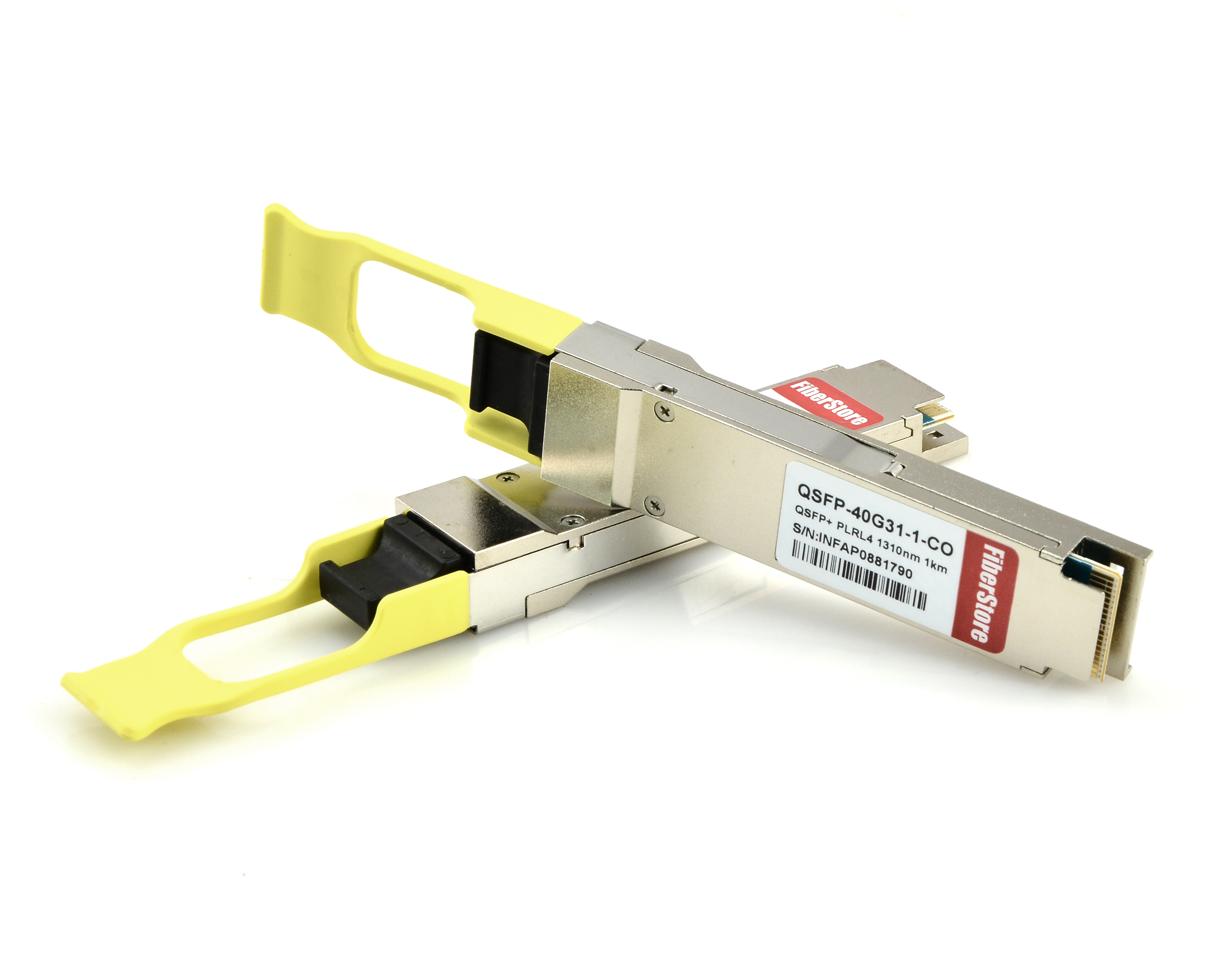
Designed with MTP interface, the parallel QSFP-4X10GE-IR transceiver offers 4 independent transmit and receive channels, each capable of 10Gbps operation. It utilizes 12-ribbon single-mode fiber cable with MTP/MPO female connector to realize 40Gbps data link with transmission distances up to 1 km.

QSFP-40G-PLRL4 Transceiver

The QSFP-40G-PLRL4 transceiver uses 12-fiber MTP interface to achieve 40Gbps parallel transmission, supporting maximum data link lengths up to 1.4 km. The cable type required for QSFP-40G-PLRL4 transceiver is an APC (angle polished connector) single-mode 12-fiber MTP cable. APC is the only available type for single-mode MTP-12 fiber.

QSFP-4X10G-LR-S Transceiver

The QSFP-4X10G-LR-S transceiver is a parallel 40Gbps QSFP+ optical module. It supports link lengths of up to 10 km on G.652 single-mode fiber. It enables high-bandwidth 40G optical links over 12-fiber parallel fiber terminated with MTP/MPO female connector. It can also be used in a 4x10G mode for interoperability with 10GBASE-LR interfaces up to 10 km.

When reading this, you may find that all these three types of 40G transceivers are designed with MTP interface and use parallel transmission. In parallel transmission, data signals are sent sequentially on the same channel. In addition, they all use 1310nm wavelength and can transfer data signals up to at least 1 km. What’s more, they are compatible with the Small Form Factor Pluggable Multi-Sourcing Agreement (MSA) and they support Digital optical monitoring (DOM).

Working Principle

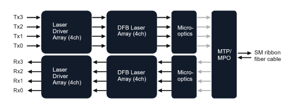
Because the structures of these three types of 40G transceivers are similar, their working principles are similar, too. The single-mode cable terminated with 12-fiber MTP connector plugged into the 40G transceiver carries the 40G signal over only 8 of the 12 fibers, remaining 4 fibers unused. The 8 used fibers are mapped as 4x10G Tx and Rx pairs. We can easily understand the working principle of these three types of 40G QSFP+ transceivers from the figure below. In the transmit side, the transmitter converts parallel electrical input signals into parallel optical signals through the use of a laser array. Then the parallel optical signals are transmitted parallelly through the single-mode fiber ribbon terminated with MTP/MPO connector. While in the receive side, the receiver converts parallel optical input signals via a photo detector array into parallel electrical output signals.

working principle of 40G QSFP+ transceiver

Application

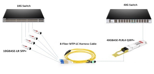
Many data centers are in the process of 10G to 40G migration. To make migration path smooth, we can use 40G transceivers together with MTP cable. Take QSFP-40G-PLRL4 transceiver for example, we can simply use MTP-LC harness cable to connect one QSFP-40G-PLRL4 transceiver and four 10GBASE-LR SFP+ transceivers. Here is a figure for you to have a better understanding of the connectivity. In addition, for 40 connectivity, we can use MTP trunk cable to connect two QSFP-40G-PLRL4 transceivers to make the optical links. Using 40G QSFP+ transceiver for high-speed long distance transmission over single-mode fiber is a cost-effective solution.

QSFP-40G-PLRL4 transceiver for 10G to 40G connectivity

Conclusion

With special structures, MTP components are popular with data center managers for fast installation, high density and high performance cabling. QSFP-4X10GE-IR, QSFP-40G-PLRL4 and QSFP-4X10G-LR-S these three 40G QSFP+ transceivers have special interface designs which can be compatible with single-mode MTP connector and support long distance transmission. During the deployment of 40G QSFP+ module, selecting proper MTP assemblies are also essential to successfully accomplish the link. The optical components mentioned above can be found in FS.COM. If you want to know more details, please visit our site.

Using EDFA Amplifier for Long-Haul CATV Systems

With Laser technology combining with fiber optic technology, CATV systems in the field of optical communication have demonstrated unprecedented and irreplaceable achievements in the past few decades. When transmitting optical signals with fibers, fiber attenuation is the main factor that limits the transmission distance. EDFA (Erbium-Doped Fiber Amplifier) designed for CATV long-haul transmission avoids the conversion of optic-electric-optic in CATV long-haul transmission. It amplifies low signal power into high signal power, thus extending transmission distance. This post analyzes EDFA configurations and the utilization in long-haul CATV systems.

EDFA Leading Position in CATV Systems

EDFA is one of the most prominent achievements in fiber optic transmission technology over the past decade. Because it cleverly combined the laser technology and optical fiber manufacturing technology in the CATV systems and its applications were then rapidly expanded. Originally PDFA and EDFA amplifiers were equally used for CATV systems, but today, EDFA has completely replaced PDFA and become the primary device for fiber optic transmission systems. Why EDFA has leading position on CATV systems? Because EDFA noise and distortion characteristics are better, and its superior characteristics can be clearly seen in the following:

  • Operates at wavelength of 1550nm, consistent with C-band where fiber has the lowest loss
  • Has higher saturation output power, useful in systems requiring transmission up to 100 km or systems requiring the optical signal to be split to multiple fiber optic receivers
  • The signal gain spectrum is wide up to 30nm or more, can be used for broadband signal amplification, especially for WDM (wavelength division multiplexing) system, ideal for radio and data services networks
  • Has user friendly interface RS232, easy to control and monitor with computers
  • Low noise figure with high stability
EDFA Configurations

The configuration of a co-propagating EDFA is shown in Figure 1. The optical pump is combined with the optical signal into the erbium-doped fiber with a wavelength division multiplexer. A second multiplexer removes residual pump light from the fiber. An in-line optical filter provides additional insurance that pump light does not reach the output of the optical amplifier. An optical isolator is used to prevent reflected light from other portions of the optical system from entering the amplifier.

EDFA Configuration-1

An EDFA with a counter propagating pump is pictured in Figure 2. The copropagating geometry produces an amplifier with less noise and less output power. The counter propagating geometry produces a noisier amplifier with high output power. A compromise can be made by combining the co- and counter-propagating geometries in a bi-directional configuration.

EDFA Configuration-2

A Typical CATV System Using EDFA

Figure 3 illustrates a basic long-haul CATV transmission system designed to carry 77 channels of CATV signals for 100 km in a basic point-to-point configuration.

CATV EDFA

As you can see in Figure 3, the local CATV provider sends 77 channels of CATV signals at the transmitting side. After processing and RF combining, those multiple signals are combined into one channel of CATV signal with the wavelengths of 1550 nm. It transmits over a single-mode optical fiber to 50 km. An EDFA amplifier is used at the middle point to amplify the signals to a certain power level, continuing to transmit over a single mode fiber to 100 km. At the receiving side, the 1550nm CATV channel is split into multiple channels of 1550nm CATV signals, serving multiple hotel cable TV users.

FS.COM CATV EDFA Optical Amplifiers List

EDFA has undoubtedly received wide interest for CATV applications because of its high output power, low distortion and low noise capability. FS.COM supplies optical amplifiers including CATV EDFA, SDH EDFA, DWDM amplifier, etc. The following table lists FS.COM CATV EDFA amplifiers which are available with range of output power from 13 dBm to 24 dBm to meet the requirements of a high-density solution for the large-scale distribution of broadband CATV video and data signals to video overlay receivers in a FTTH/FTTP or PON system.

Product ID Part Number Description
17467 CEDFA-O13 New 13dBm 1550nm CATV EDFA Fiber Optic Amplifier
17489 CEDFA-O17 New 17dBm 1550nm CATV EDFA Fiber Optic Amplifier
17495 CEDFA-O23 New 23dBm 1550nm CATV EDFA Fiber Optic Amplifier
36458 CEDFA-BA Customized 1550nm CATV EDFA Fiber Optic Amplifierr