Category Archives: Cat5e Cables

Ethernet Patch Cable Wiring Guide

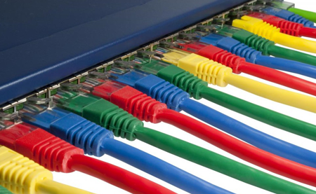
Ethernet patch cable has already become a ubiquitous part of our everyday experience. It is generally used for connecting virtually all networking components, providing a flexible and cost-effective way of transmitting voice, data, and multimedia over integrated networks. When dealing with Ethernet patch cables, we sometimes get confused regarding patch cable wiring schemes and when they should be employed. So this article will try to shed some light on this commonly confused subject.

ethernet patch cable

Ethernet Patch Cable and Wiring Standard

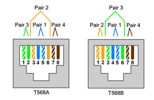
Since the wiring scheme of different Ethernet patch cable varies, we’ d better get to know the categories of it as well as its wiring standard. Basically, Ethernet patch cable comes in two types: straight-through cables and crossover cables. As for the wiring standard, there existing T568A and T568B defined in the ANSI/TIA-568-C.2 standard for 4-pair (8-position, 8-conductor) RJ45 interfaces. When used in traditional fashion, there is no functional difference between patch cords with T568A or T568B wiring standards. Both wiring standards are acceptable and are essentially interchangeable. The only difference between T568A and T568B specification is the orientation of the green and orange wire pairs.

T568A-T568B-ethernet-cable-wiring-standard

Ethernet Patch Cable Wiring Scheme

In the previous part, we have mentioned the common types of Ethernet patch cables. So next we will further explain their features and illustrate the wiring scheme of each in details.

Straight-Through Cables

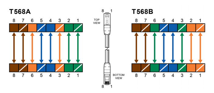
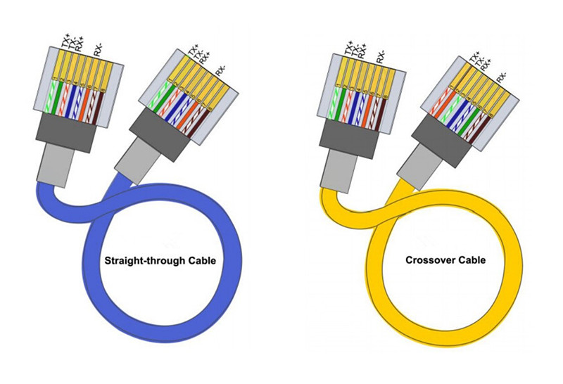
Straight-Through cables get its name due to the fact that both of its ends are configured in the same way. This kind of Ethernet patch cable often adopts the same wiring standard: either T568A or T568B layout. Which means out of the 8 pins on both ends of an Ethernet cable, each pin connects to the same pin on the opposite side. Most Ethernet patch cables on the market are straight-through cables, and they are typically used to connect unlike devices, such as connecting a router to a hub, a computer to a switch and a LAN port to a switch, hub or computer.

straight-through ethernet patch cable

Crossover Cables

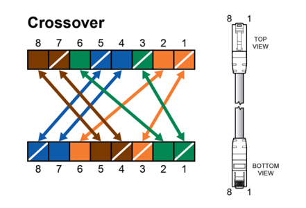
Judging from the physical appearance, crossover cables just resemble that of the straight-through cables. However, the difference actually lies in the order that the wires are arranged: the send and receive pairs in this cable are crossed from one module plug to the other. Crossover cables use two different wiring standards: one end uses T568A wiring standard, while the other applies T568B wiring standard. This Ethernet patch cable is preferred for direct connection between the same devices: a PC to another PC, a hub to hub or switch to switch.

crossover ethernet cable

How to Distinguish Ethernet Patch Cable?

Knowing the difference between the two types of Ethernet patch cables is proved to be useful, especially when connecting them to various components. Let’ s see how to efficiently identify each.

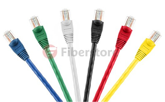
The easiest way to tell what kind of Ethernet patch cable you have is to look at both of its ends together. If both cable ends are configured according to the T568A or T568B standard for both connector ends, then the cable is a straight-through patch cord. But if the patch cable is wired according to the T568A standard at one end, and the T568B at the other end, the cable is a crossover cable. Crossover cables sometimes have orange or yellow sheaths to make them easier to identify.

ethernet network cable

Conclusion

Ethernet patch cable facilitates our life in various aspects, and it also has played a significant role in the development of generic and structured cabling system. I hope this article could help to eliminate any confusion with regard to the features and wiring schemes of different Ethernet patch cables. FS.COM offers a wide range of Ethernet cables (Cat5e/Cat6/Cat7) and accessories. For more information and tutorials, visit www.fs.com.

Cabling for Successful Power Over Ethernet (PoE) Installation

The demand for connection from network equipment and devices is accelerating continuously nowadays. And it inevitably leads to the rising cost and complexity of deployment. Therefore, Power over Ethernet (PoE) technology that uses a single twisted-pair cable to provide both data connection and electrical power to devices is employed, for the purpose of less cable usage and investment. PoE has taken a giant leap recently, and we will discuss connectivity and cabling tips for achieving successful PoE deployment in this article.

A Common Description of PoE

Power over Ethernet, often referred to as PoE, is a low voltage technology. It describes a system to safely deliver DC electrical power, along with data, to remote devices over standard data-com cabling or Ethernet cabling. Commonly known as Cat5e or Cat6 cables. PoE has taken a giant leap recently, since it obtains some appealing advantages:

Power over Ethernet (PoE) definition

Time and cost savings—by reducing the time and expense of installing electrical power cabling. Network cables do not require a qualified electrician to fit them, and can be located anywhere.

Flexibility— without being tethered to an electrical outlet, devices can be located wherever they are needed most, and repositioned easily.

Safety—PoE delivery is intelligent, and designed to protect network equipment from overload, under powering, or incorrect installation.

Reliability—PoE power comes from a central and universally compatible source. It can be backed-up by an uninterruptible power supply, or controlled to easily disable or reset devices.

Scalability—having power available on the network means that installation and distribution of network connections are simple and effective.

How Does PoE Work?

Power over Ethernet (PoE) demands for a powered device (PD) and power sourcing equipment (PSE) contained in the solution. This ensures that the solution is a complete circuit. A PSE is located at the originating end and generates power and data. The PSE transfers power and data through cat5e or cat6 cable, and delivers it to the PD. The PD serves as an end device that accepts the power and data from the PSE.

Power over Ethernet (PoE)

Currently Approved PoE Standards

Recent PoE standards enable higher power transmission, which expands the range of devices supported in the enterprise, and to some extent, resulting in the boom of PoE adoption rates. However, higher current PoE brings critical cabling and connectivity considerations when ensuring maximum performance in the network.

Power over HDBASET (PoH) delivers video, audio, 100Mbit/s Ethernet, and power. The POH standard is based on the 802.3at standard, modified to enable delivery of up to 100 W over 4-pair Cat 5e or 6. And TIA and ISO are also currently updating standards that address cabling to support 4-pair PoE in accordance with 802.3bt. TIA TSB-184 guidelines for supporting power delivery over balanced twisted-pair cabling, and ISO/IEC 11801-6 distributed building services working draft are raising requirements to Cat6a cabling to better support IEEE 802.3bt four-pair PoE, as well as other applications.

Cabling for PoE

The heat generation in cable bundles can actually influence network performance to a large extent. High temperatures can lead to higher insertion loss, shorter permissible cable lengths, and higher power costs due to more power dissipated in the cabling. Cable temperatures should not exceed the temperature rating for the cable. The Telecommunications Industry Association (TIA) recommends 15 degrees as the maximum allowed temperature rise above ambient as a result of power over the cabling.

Here are two tips to help lower cabling temperature in PoE deployment:

Tip One: Reduce the Number of Cables Per Bundle

Separating large cable bundles into smaller bundles or avoiding tight bundles helps to minimize higher temperatures. For example, the temperature of a bundle of 91 cables is higher compared to three bundles of 37 cables. And physically separating the three bundles from each other further reduced the maximum temperature.

Tip Two: Use Higher Category Cabling

Higher category-rated cable typically means larger gauge sizes, and as power currents increase, these larger conductors will perform better than smaller cable. The TIA test indicates that higher category-rated cable allowed for larger bundle sizes under the maximum 15-degree temperature increase. The allowable bundle size was 52 cables for Cat5e, 64 for Cat6, 74 for Cat6a. Meanwhile, higher-category cabling is capable of supporting more current capacity at the maximum allowable 15 degrees. (see the figure below).

Cat5-5e-6a

It is thus clear that higher category cabling is vital to minimize temperature increases. So Cat6a is recommended for all new installations due to the fact that it supports the highest data rate of 10GBASE-T, and has no bundle size limitations with any current or future PoE application.

Cat6a cable

Conclusion

High quality cabling serves as the fundamental elements for attaining the performance, reliability, and flexibility needed in the PoE. Hence, when cabling for PoE, try to reduce the number of cables per bundle to minimize temperatures. And it is also necessary to choose higher category cabling that allows for larger bundle size and to ensure more current capacity.