Connectors are used to mate two fibers to create a temporary joint and/or connect the fiber to a piece of network device. That’s one of fiber termination ways. The primary specification of connector termination is loss or the amount of light lost in the connection. Connector loss can be caused by a number of factors. This article will talk about the influence of fiber connector polish type on connector termination.
When the cone of light emerges from the connector, it will spill over the core of the receiving fiber and be lost. In addition, the end gaps can arouse the other problem called reflectance. The air gap in the joint between the fibers causes a reflection when the light encounters the change of refractive index from the glass fiber to the air in the gap. This reflection is called to as reflectance or optical return loss, which can be a problem in laser based systems.
Nowadays the fiber optic connectors have several different ferrule shapes or finishes, usually referred to as end finish or polish types. The connector end face preparation will determine the connectors’ return loss, also known as back reflection. Different end face causes different back reflection.
The Physical Contact (PC) polish results in a slightly curved connector surface, forcing the fiber ends of mating connector pairs into physical contact with each other. This eliminates the fiber-to-air interface and results in back reflections of -30 to -40 dB. The PC polish is the most popular connector end face, used in most applications.
In the Ultra PC (UPC) polish, an extended polishing cycle enhances the surface quality of the connector, resulting in back reflections of -40 to -55 dB and < -55dB, respectively. These polish types are used in high-speed, digital fiber optic transmission systems.
Later, it was determined that polishing the connector ferrules to a convex end face would produce an even better connection. The convex ferrule guaranteed the fiber cores were in contact. Losses were under 0.3dB and reflectance -40 dB or better. This solution is to angle the end of the ferrule 8 degrees to create APC or angled PC connector. Then any reflected light is at an angle that is absorbed in the cladding of the fiber, resulting in reflectance of >-60 dB.
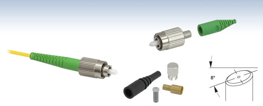
As the introduction of fiber optic technology, numerous connector styles have been developed – probably over 100 designs. Each connector style is designed to offer better performance (less light loss and reflectance) and easier, faster and/or more inexpensive termination. For example, FC–“Ferrule Connector”. The following are three common types of FC connectors:
- FC/PC–It’s the most common of the FC connectors. The tip is slightly curved to ensure only the fiber cores make connection during mating not the ferrules themselves. The return loss is 25-40 dB.
- FC/UPC–The higher quality polish with rounder edges than FC/PC ensures better core mating. The return loss is 45-50 dB. It can mate with FC/PC connectors.
- FC/APC–Common in most single mode applications where back reflection is critical to be minimized. Identified by the 8 degree of angle present in the ferrule tip along with a typical green colored strain relief boot. The return loss is 55-70 dB. It can only mate with other FC/APC fibers.
From this article, you can see the connector with APC polish type can provide the best connection. Later when you face many different types of fiber optic connectors, you may take polish type as one of the factors to make your decision.
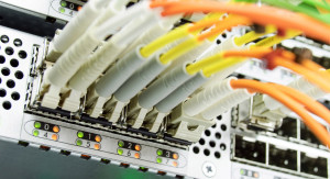 LC connector
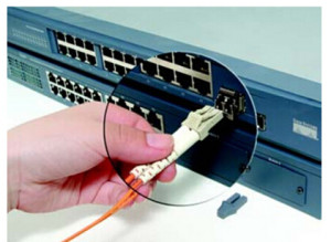 In the emerging SFF connector landscape, the LC connector is clearly the leader in performance as well as installed base. Since the LC connector has been licensed widely and is now offered by most major cabling system vendors (including some early proponents of MT-RJ), the exact number of LC connectors shipped is difficult to ascertain. However, at least one vendor has shipped over 24 million LC connectors, with a mix of approximately 60% multi-mode and 40% single-mode. The MT-RJ connector places a distant second in both performance and installed base. The multi-mode version has found some support with a few large transceiver vendors and LAN equipment manufacturers, particularly for the less demanding 100BASE-FX interfaces. However, the LC connector is quickly becoming the preferred transceiver connector for high bit rate applications (1 Gb/s and above) due to its numerous advantages for transceiver design. More transceiver manufacturers support the LC interface than any other SFF connector, and LC transceivers are available from numerous sources for applications ranging from 10 Mb/s to 10 Gb/s.