Tag Archives: fusion splicing

Why Not Consider Splice-On Connector for Field-Termination?

There is no question that the demand for network capacity is accelerating dramatically as data traffic has proliferated. Hence, a great amount of optical fibers are deployed in the field in order to cope up with the requirements. Which inevitably exerts more work stress when polishing and terminating these massive fibers. Field-installable splice-on connectors, which can be terminated at the end of the cable in field by fusion splicing, can resolve this issue. This article will shed light on the functions and benefits of splice-on connector, and explain why we should consider it seriously.

sc type splice-on connector

What Is Splice-On Connector?

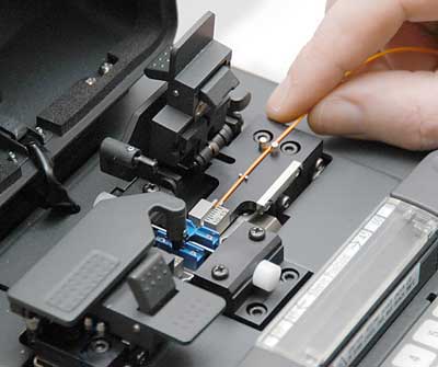
A splice-on connector uses a fusion splicer to permanently join a fiber stub inside the connector with a fiber cable. The splice is protected within the boot of the connector. Splice-on connector features a factory pre-polished ferrule that eliminates the need for polishing and adhesives so they can be crimped in the field. Splice-on connectors significantly enhance the effectiveness of the termination and installation, which allow for unsurpassed performance and flexibility in the field. Moreover, splice-on connectors are easily assembled that requires minimal skill or training, and it presents the same high quality as the factory terminated one.

splice-on connector structure

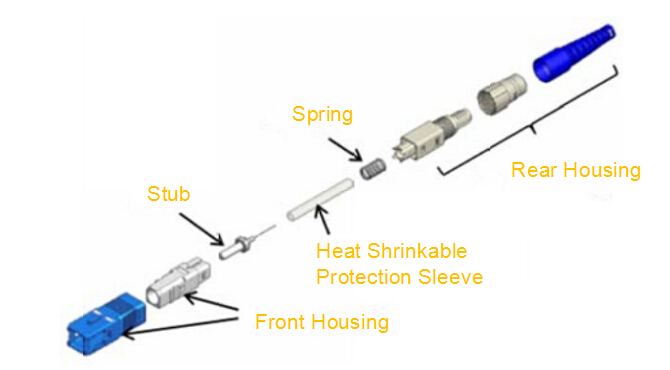
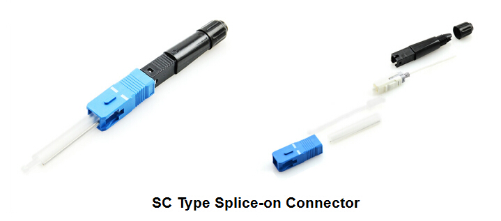
The diagram above typically illustrates the SC type of the field-installable splice-on connector. It generally consists of 8 parts. In addition to stub, which is a ferrule with a short fiber, and heat shrinkable sleeve, all housing parts are almost the same design as the standard connector.

How to Assemble Splice-On Connector?

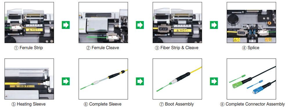
The process for splice-on connector assembly is fairly easy, and SC or LC version simply has the same procedures. Here we take SC splice-on connector for example, just follow these steps:

splice-on connector assembly procedure

Why to Consider Splice-On Connector?

Splice-on connectors generally expand our options for field-termination, technicians nowadays incline to embrace the splice-on connector for OSP environment, data center installation and multi-dwelling unit (MDU) networks. Here are six reasons why we should consider splice-on connector to network.

Fewer Components and Material Required

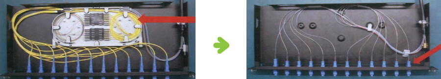
With a splice-on connector, the pigtail is eliminated since the fiber stub inside the connector is permanently joined with a fiber cable. The splice is protected within the connector boot. There is no need for splice tray, slack management of fiber strands, or other accessory.

pigtail splice vs. splice-on connector in cassette

Better Insertion Loss and Return Loss

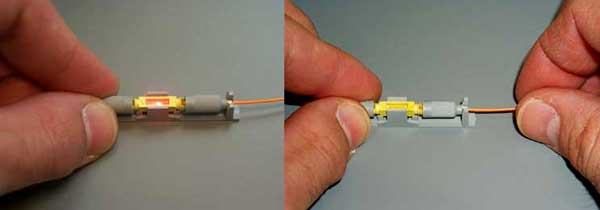
Splice-on connector has better performance on insertion loss and return loss when compared with mechanical splice. By utilizing a fusion splicer, a splice-on connector creates a continuous connection in the glass by “welding” cores together. Which results in robust performance at the splice.

Installation Flexibility

Splice-on connector gives installer much more flexibility by combining fusion splicing with a field-installable connector. It allows you to run drop cables to an end-user, cut the length you need and then attach the splice-on connector and plug it in, with no shorts or excess slack. Splice-on connector makes it possible to achieve durable, high-performance connection with the same amount of time it takes to complete a mechanical splice.

splice-on connector installation flexibility

Well-Suited for Outdoor Environments

Most splice-on connector can be used in outdoor environments, providing permanent, robust connections in outdoor enclosures. They can remain stable through a wide range of temperatures and other harsh conditions.

Notification for Successful Splice

When technician successfully completes the splicing task, most fusion splicer can notify them. This decrease the chance for installer skill that is required for mechanical splicing, making it easy to use splice-on connectors regardless of you are a beginner or expert.

Significantly Decreased Price

The cost of fusion splicing tools once has stood in the way for the spread of fusion splicing. However, the industry has experienced significant decreases in splice prices in recent years. One can even choose to rent those devices if needed. Fusion splicing gains in much popularity that enables more installers to benefit from splice-on connectors for deployments.

Conclusion

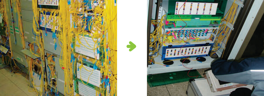
Splice-on connectors simply combine the quality of fusion splicing with the ease of a field-installable connector. It enables technicians to realize greater efficiency and improve fiber management especially in tight space and high density environments. They have been extensively used in FTTx networks, cable TV backbone networks, outside plant and MDU FTTP cabling, as well as data center installation and connector restoration in the field. So why not consider splice-on connectors for your project?

An Overview of Fiber Optic Splicing

It is generally accepted that splicing is often required to create a continuous optical path for optical pulses from one fiber length to another. Thus, relevant skills and knowledge of fiber optic splicing methods have become increasingly essential to any company or fiber optic technician specialized in telecommunication or LAN and networking projects. Under some circumstances, fiber optic cables may need to be spliced together to ensure better performance, such as to achieve a connection of a certain length, or just to repair a broken cable. For example, the maximum lengths of a fiber optic cable is up to about 5 km, then two fiber optic cable need to be spliced together to achieve 10km lengths of data transmission. This article aims to describe some basic elements related to optical fiber splicing thus to provide useful information about it.

What Is Fiber Optic Splicing

Just as the name indicates, fiber optic splicing serves as a method to join two optical fiber together due to some necessary reasons. Fiber optic splicing typically lead to lower light loss and back reflection than termination, making it a relatively preferred method when the transmission distances are too long for a single length of fiber or when one have to joint two different types of cable together, such as a 48-fiber cable to four 12-fiber cables. Besides, splicing is also used to restore or repair fiber optic cables when a buried cable is accidentally broken or damaged.

The Types of Fiber Optic Splicing

Basically, there exist two fiber interconnection methods: one is fusion splicing and the other is mechanical splicing. If you are just beginning to splice fiber, you might need to look at your long-term goals in this field in order to choose which technique best fits your economic and performance expectations.

Fusion splicing remains to be one of the most widely adopted permanent technique to joint optical fibers, which contains the process of fusing or welding two fibers together usually by an electric arc. The popularity of this kind of splicing method is resulted from the lowest loss and least reflection it offers. Moreover, it also provides the strongest and most reliable joint between two fibers. Fusion splicing can be achieved by a specialized equipment called fusion splicer that generally involves two functions: aligning the fibers and then melting them together.

Fusion fiber optic splicing

Mechanical splicing, on the other hand, is simply aligned and designed to hold in place by a self-contained assembly. Two fibers are not permanently joined, just precisely held together to enable light to pass from one fiber into the other. Mechanical splicing are especially popular for fast, temporary restoration or for splicing multimode fibers in a premises installation. Meanwhile, they are also used as temporary splices for testing bare fibers with OTDRs or OLTSs.

Mechanical splices generally have higher loss and greater reflection than fusion splices, but they do not need an expensive machine to fulfill the splicing tasks. All needed are just a simple cleaver and some cable preparation tools. Sometimes, a visual fault locator(VFL) may help to optimize some types of splices.

Mechanical fiber optic splicing

The Procedures of Fiber Optic Splicing
Both of fusion splicing and mechanical splicing consist of four basic steps, and for the first two steps, these two splicing methods are relatively the same. They only differ from each other in the last two steps.

Four basic steps to achieve a proper fusion splicing:

Step 1: Preparing the fiber- Striping the protective coatings, jackets, tubes, strength members, etc. leaving only the bare fiber and keeping it clean.

Step 2: Cleaving the fiber-Using a good fiber cleaver is essential to ensure a successful fusion splice. The cleaved end must be mirror-smooth and perpendicular to the fiber axis to obtain a proper splice.

Step 3: Fusing the fiber-Two steps involves in this step: alignment and heating. Alignment can be manual or automatic depending on what equipment you have. Once properly aligned the fusion splicer unit then uses an electrical arc to melt the fibers, permanently welding the two fiber ends together.

Step 4: Protecting the fiber-Protecting the fiber from bending and tensile forces will ensure the splice not break during normal handling. A typical fusion splice has a tensile strength between 0.5 and 1.5 lbs and will not break during normal handling but it still requires protection from excessive bending and pulling forces. Using heat shrink tubing, silicone gel and/or mechanical crimp protectors will protect the splice from outside elements and breakage.

Four basic steps to complete a mechanical splicing:

Step 1: Preparing the fiber -Striping the protective coatings, jackets, tubes, strength members, etc. leaving only the bare fiber and keeping it clean.

Step 2: Cleaving the fiber-The process is identical to the cleaving for fusion splicing but the cleave precision is not as critical.

Step 3: Mechanically join the fibers-No heat is needed in this method. Simply position the fiber ends together inside the mechanical splice unit. The index matching gel inside the mechanical splice apparatus will help couple the light from one fiber end to the other. Older apparatus will have an epoxy rather than the index matching gel holding the cores together.

Step 4: Protecting the fiber-The completed mechanical splice provides its own protection for the splice.

Conclusion

From what discussed above, we can figure out that these two types of fiber optic splicing methods obtain their advantages and drawbacks. Whether to fusion splicing or mechanical splicing in fact depend greatly on several elements, such as transmission distance, signal loss and reflection requirements. For most telecommunication and CATV companies, they incline to invest in fusion splicing for their long haul single-mode network. While in terms of shorter, local cable runs, they still prefer mechanical splicing. However, since signal loss and reflection are minor concerns for most LAN applications, either of these two methods can be equally employed in the LAN industry.