Category Archives: Optical Amplifiers

Passive Optical Amplifiers: EDFA, SOA and RFA

As optical signals travel through an optical fiber, they are attenuated. In long-haul applications, the signal is attenuated to the point where re-amplification is required. Traditionally, a device commonly referred to as a repeater accomplished this re-amplification.

A repeater is basically a receiver and transmitter combined in one package. The receiver converts the incoming optical energy into electrical energy. The electrical output of the receiver drives the electrical input of the transmitter. The optical output of the transmitter represents an amplified version of the optical input signal plus noise.

The technology available today eliminates the need for repeaters. Passive optical amplifiers are now used instead of repeaters. A passive optical amplifier amplifies the signal directly without the need for optical-to-electric and electric-to-optical conversion. There are several different optical amplifiers with which to passively amplify an optical signal: Erbium Doped Fiber Amplifier (EDFA), Semiconductor Optical Amplifier (SOA), and Raman Fiber Amplifier (RFA), all of which use a technique called laser pumping.


EDFA

EDFA amplifier is generally used for very long fiber links such as undersea cabling. The EDFAs use a fiber that has been treated or “doped” with erbium, and this is used as the amplification medium. The pump lasers operate at wavelengths below the wavelengths that are to be amplified. The doped fiber is energized with the laser pump. As the optical signal is passed through this doped fiber, the erbium atoms transfer their energy to the signal, thereby increasing the energy or the strength of the signal as it passes. With this technique, it is common for the signal to be up to 50 times or 17dB stronger leaving the EDFA than it was when it entered.

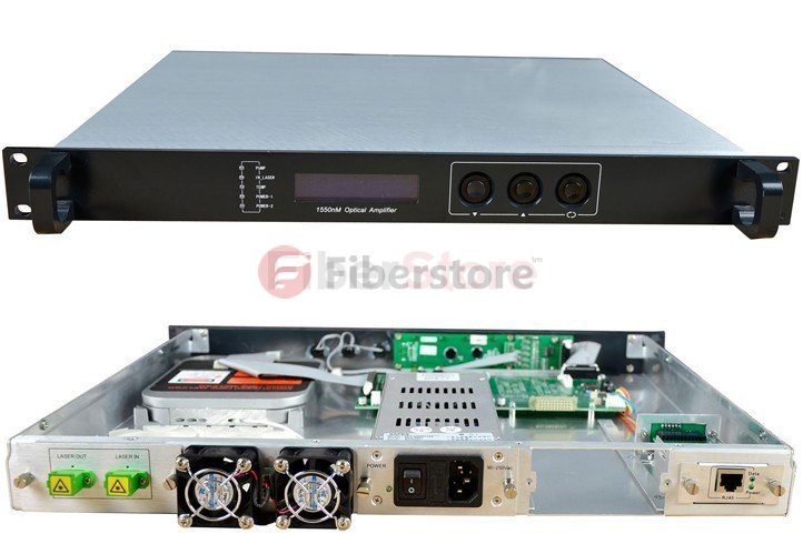
Here is an example of an EDFA. EDFAs may also be used in series to further increase the gain of the signal. Two EDFAs used in series may increase the input signal as much as 34dB.

EDFA technique


SOA

SOA amplifier uses a technique similar to that of EDFA but without doping the optical fiber. Unlike the EDFA, which is energized with a laser pump, the SOA is energized with electrical current. The SOAs use an optical waveguide and a direct bandgap semiconductor that is basically a Fabry-Pérot laser to inject light energy into the signal, as shown in the figure below. This technique, however, does not offer the high amplification that the EDFAs do. SOAs are typically used in shorter fiber links such as Metropolitan Area Networks (MANs).

SOA technique

One problem with SOAs is that the gain is very hard to control. By using the semiconductor technique and a waveguide, the signal may deplete the gain of a signal at another wavelength. This can introduce crosstalk among channels by allowing the signal at one wavelength to modulate another.


RFA

RFA amplifier uses a technique called Raman amplification which is a method that uses pump lasers to donate energy to the signal for amplification. However, unlike EDFAs, this technique does not use doped fiber, just a high-powered pumping laser, as shown in the figure below. The laser is operated at wavelengths 60 nm to 100 nm below the desired wavelength of the signal. The laser signal energy and the photons of the transmitted signal are coupled, thereby increasing the signal strength. RFAs do not amplify as much as the EDFAs, but they have an advantage in that they generate much less noise.

RFA technique

These optical amplifiers can be combined to take advantage of their amplification characteristics. In some cases, RFAs and EDFAs are combined in long-haul fiber links to ensure high amplification and decreased noise levels.

In summary, each amplification technique has advantages and disadvantages. Remember to keep in mind the amplification that the amplifier is being used in. For example, if a signal needed amplification but noise was an issue, a RFA amplifier would most likely be the best choice. If the signal needed to be amplified by just a small amount, the SOA amplifier might be best.

All of these amplification methods have one big advantage: optical amplifiers will amplify all signals on a fiber at the same time. Thus, it is possible to simultaneously amplify multiple wavelengths (e.g, the DWDM EDFA is a type of WDM amplifier used to amplify multiple wavelengths in DWDM systems). But it is important to keep in mind that the power levels must be monitored carefully because the amplifiers can become saturated, thereby causing incorrect operation.

We Need to Know the Two Types of Optical Amplifiers

Wideband amplifiers

In response to the exponential growth in data traffic, optical networks were designed with a growing number of dense wavelength division multiplexing DWDM Channels. State-of-the-art commercial DWDM systems include EDFAs able to support up to 160 channels with 50 GHz channel spacing spanning both C- and L-band. However, the deployed networks predominantly consist of channels in the C-band, Some geographical areas such as Japan have deployed DWDM Optical Amplifiers to support transmission systems in the L-band over the dispersion shifted fiber spans. Moreover, the use of a hybrid design of EDFAs in conjunction with Raman amplifiers is prevalent in special networks with ultra-long spans.

Agile amplifiers

There is a large market for optical amplifier that until recently was driven by static point-to-point WDM system application. However, the increasing unpredictability of traffic demand and the emergence of bandwidth-hungry applications such as video on demand have recently turned the industry’s focus to dynamic, reconfigurable optical networks based on RAODMs to route different wavelength channels, including DWDM wavelength channels and CWDM wavelength channels. Sales of ROADMs are increasing with a compound annual growth rate exceeding 40%; by the end of 2010 the number of field deployed wavelength selective switches (WSS), a key component of modern ROADMs, is expected to exceed 100,000. Essentially all new metro, regional, and long-haul WDM system products developed by equipment manufacturers, such as DWDM Equipment Manufacturers, which offers ROADM-based wavelength agility as a key feature. Similarly, all network deployments planned ny Tier-1 carriers in the major industrial nations and many in emerging nations require reconfigurable wavelength agility to reduce operational expenses and increase service velocity. A recent report from Ovum-RHK concluded that ROADMs and agile EDFAs lead the transition to a dynamic optical network. The report forecast that the growth of these two components will track each other closely with over 80% of 2010 module sales in both categories expected for agile components.

This has created new challenges for the design of amplifiers including, for example, those related to dynamics and control of transients, spectral hole burning, and polarization-related impairments. Introduction of channels at higher data rates employing a coherent receiver, followed by high-speed digitization and rates employing a coherent receiver, followed by high-speed digitization and signal processing, can pose additional constraints on the system tolerance due to their sensitivity to channel power fluctuation caused by transients. Increasing the optical amplifier technical literature and commercial practice have dealt with such design challenges posed by dynamic, reconfigurable optical networks. Today specifications for new optical amplifier designs are almost always framed to support the requirements of reconfigurable optical networks.

These developments have led to the realization that the optical amplifiers constituting the transmission path need to provide performance agility in order to provide high-quality service for the channel traffic propagating through the amplifier. In the network architecture, two types of events have to be considered: intentional reconfiguration or re-provisioning and unintended failures or faults leading to protection path switching. In both types of events the optical amplifiers in the transmission path need to have fast gain control, which is usually implemented via electronic control of the amplifier’s pump lasers.

In order to effectively control the power transients in DWDM systems, it is important to understand the factors that influence the speed or the rate at which the surviving channel powers change during transients. This speed depends on both the DWDM EDFA characteristics and the number of EDFAs constituting the system. In a single EDFA, the time constant of the power transients decreases with increases in saturated power output. In a system with long chains of EDFAs constituting the system. In a single EDFA, the time constant of the power transients decreases with increases in saturated power output. In a system with long chains of EDFAs, the amplifiers strive to maintain the saturated output power levels. The time varying output of the first EDFA (after a fiber span loss) appears as an input to the second EDFA, which has time-dependent gain, and therefore the output power of the second EDFA changes at a faster rate. Consequently, with increasing numbers of amplifiers in the chain, the speed of transients becomes faster and faster, thereby requiring control on shorter and shorter time scales to limit the power excursion of surviving channels. Proper transient control design needs to take into account the fastest single event in the network as well as the acceleration of this event due to the cascading of amplifiers.

DWDM EDFA optical amplifiers

Another important characteristic for the control of the transients is the slew rate associated with the event causing a change in the channel loading of amplifiers which determines the rate of the surviving channels’ power change during transients. Events such as failure of a transmitter laser can happen by mistake, typically occur over hundreds of μm, whereas fiber breaks often happen by mistake, typically occur over hundreds of milliseconds (ms) or even seconds, although in a rare worst case they can be much faster. Likewise, provisioning of channels can be implemented in a controlled fashion, one at a time, to minimize sudden changes in the power of the transmitting channels. The state-of the art switching technologies currently being implemented in ROADMs also have transition times of hundreds of milliseconds.

Fiberstore is a quite reliable for its quality of optical fiber products, the good news is that it is working with 30% of the price discount, so if you need some CWDM/DWDM products or other optical fiber products, hurry up and take an action! The website: http://www.fs.com/