Tag Archives: MPO breakout cable

Why Short Distance MTP-based Connectivity Utilizes OM3 or OM4 Fibers?

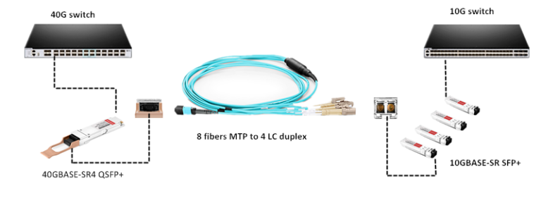
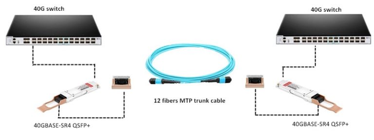
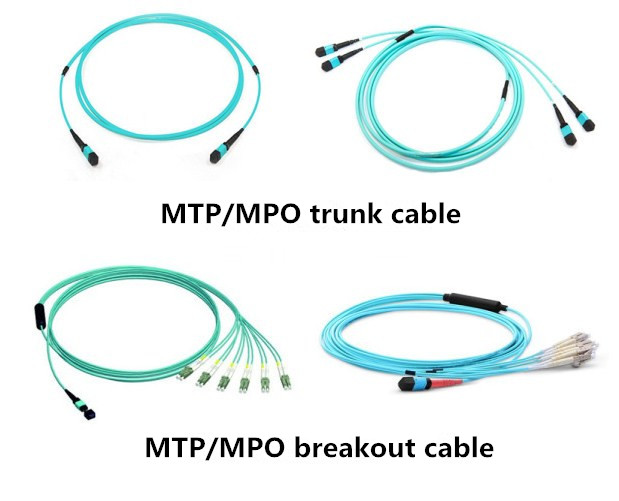
As today’s network needs to support more devices and advanced applications than ever before, the amount of data transmitted at the enterprise business level is rapidly climbing. For many data centers, 10G network no long satisfies the need of high speed data transmission. In 2010, the IEEE ratified the 40G ad 100G standard. Then how to realize smooth migration path from 10G to 40G and 100G has become the most concern for data center managers. After some comparison, many data center managers turn to MTP-based connectivity since it can provide fast installation, high density and high performance cabling for data centers. It is not difficult to find that both MTP/MPO trunk cable and MTP/MPO breakout cable (shown as the figure below) used for short distance connectivity utilize OM3 or OM4 fibers. Why short distance MTP-based connectivity utilizes OM3 or OM4 fibers? This article will show you the reason.

MTP MPO trunk cable and MTP MPO breakout cable

Bandwidth

OM3 and OM4 fibers are the only multimode fibers included in the 40/100G standard. Multimode fibers utilize parallel optical transmission instead of serial transmission due to the 850 nm VCSEL (vertical cavity surface emitting laser) modulation limits. And OM3 and OM4 fibers have a minimum 2000 MHz∙km and 4700 MHz∙km effective modal bandwidth (EMB). The minimum EMBc (Effective Modal Bandwidth calculate) method measures the actual fiber bandwidth performance, recognizing the fact that overall system bandwidth is a function of both the bandwidth properties of the fiber and also the particle characteristics of individual laser sources, and this is the most significant factor in determining link performance. In addition, the IEEE model is the industry reference point for calculating the maximum achievable Ethernet link distance and sets out the minimum requirements of components in an optical link. Therefore, knowing the exact minimum bandwidth performance of OM3 and OM4 fibers is a prerequisite to understand the ultimate limitation of MTP-based connectivity, which can ensure the optical infrastructure deployed in the data center will meet the performance criteria set forth by IEEE for bandwidth.

Insertion Loss

No matter what kind of cabling system you are going to deploy, insertion loss is inevitable and it is an essential performance parameter of the network deployment. It is important to note that the total connectivity loss within a cabling system has an effect on the network performance over the maximum link distance at a given data transmission rate. It is not difficult to understand that the higher the total connectivity loss, the shorter the maximum link distance. As a result, the insertion loss specifications of components used for connectivity should be evaluated at first when designing data center cabling infrastructures. The 40G standard specifies that with link distance up to 100 meters, the maximum channel loss of OM3 fiber is 1.9 dB, which includes a 1.5 dB total connectivity loss budget; while for OM4 fiber, it is specified that with link distance up to 150 meters, the maximum channel loss is 1.5 dB, which includes a 1.0 dB total connectivity loss budget. And the maximum attenuation of fiber optic cable at 850 nm is 3.5 dB/km. With low-loss OM3 and OM4 fibers, maximum flexibility can be achieved with the ability to utilize MTP connector in the optical link.

Conclusion

With 850nm EMB of 2000 MHz∙km and 4700 MHz∙km, OM3 and OM4 fibers can provide the bandwidth which is needed in MTP-based connectivity for 40G network. Besides, low-loss within cabling system is another characteristic of OM3 and OM4 fibers, which can ensure the high performance of the network deployment. Therefore, utilizing OM3 and OM4 fibers makes short distance MTP-based connectivity an ideal solution for migration from 10G to 40G in data centers.

Talk About Base-8 Connectivity and Base-12 Connectivity

The technology behind data center switches, servers and transceivers is changing quickly to accommodate the ever-increasing adoption of cloud computing, along with a growing demand for high-bandwidth applications. As 40G network has been utilized by many data centers, two types of cabling solutions are popular among data center managers—Base-8 connectivity and Base-12 connectivity. How much do you know about these two cabling solutions? This article aims to talk about Base-8 connectivity and Base-12 connectivity for network applications in detail.

Base-8 Connectivity

Base-8 connectivity builds optical links on increments of the number “eight”. In Base-8 connectivity, 8-fiber MTP trunk cable, 24-fiber or 32-fiber MTP trunk cable can be used to transmit data. Base-8 connectivity provides the most future-ready solution to support high data rate transmission requirements, and the benefits are clear. It allows for 100% fiber utilization for 4-channel (SR4, PSM4, etc.) and 8-channel (SR8, LR8) applications. In addition, it eliminates conversion modules which can reduce link attenuation by 50% and enables longer parallel link distances. Base-8 connectivity will be the cleanest path from 10G to 40G and beyond regardless of protocol.

Application of Base-8 Connectivity

Many data centers are in the process of 10G to 40G migration, and Base-8 connectivity can provide a simple and reliable solution—using the MTP/MPO breakout cable. As shown in the following picture, one 40GBASE-SR4 QSFP+ transceiver is plugged in the QSFP+ interface on the 40G switch on one side, while four 10GBASE-SR SFP+ transceivers are plugged in the SFP+ interfaces on the 10G switch on the other side. Then the MTP to LC breakout cable connects the 40GBASE-SR4 QSFP+ transceiver with the four 10GBASE-SR SFP+ transceivers. Finally, the data can be transmitted from 10G switch to 40G switch through the MTP to LC breakout cable smoothly.

application of Base-8 connectivity

Base-12 Connectivity

Base-12 connectivity makes use of fiber optical links based on increments of 12 fibers. And 12-fiber or 24-fiber MTP connector assemblies are usually used to accomplish the links, such as 12-fiber or 24-fiber MTP trunk cable. When using Base-12 connectivity, a larger number of fibers can be installed quickly because the 12-fiber or 24-fiber MTP connector can provide higher fiber cabling density. However, in Base-12 connectivity, four fibers for transmit and four fibers for receive, leaving four fibers unused per connection. In spite of this, Base-12 connectivity in some cases may still be more cost-effective which can meet the newer 40G/100G standard format.

Application of Base-12 Connectivity

For 40G network, 12-fiber MTP trunk cable can provide the simplest way. As shown in the following picture, two 40GBASE-SR4 QSFP+ transceivers are separately plugged in the QSFP+ interface on the 40G switch on each side. Then the 12-fiber MTP trunk cable connects the two 40GBASE-SR4 QSFP+ transceivers. Finally, the 40G optical link is accomplished.

application of Base-12 connectivity

Conclusion

Both Base-8 connectivity and Base-12 connectivity have their own benefits. Though Base-8 can realize 100% fiber utilization in cabling system, it is not an universal solution. While Base-12 connectivity in some cases may still be more cost-effective. As for which one to choose, it depends on the requirements of the network deployment. I hope this article can help you have a better understanding of this two cabling solutions.