We are now basking in a great boom in data transmission and information exchange, which results in an ever growing demand for higher speed and more reliable network. Currently, to migrate from legacy 10G to 40/100G network has become a hot topic yet irreversible trend. Part of this evolution, of course, was installing fiber optics in more network interconnection scenarios instead of copper cable. Among various connectivity methods, fiber optic cables have become the ubiquitous transport medium in the data center network. So, when employing fiber optic cable for 40/100G migration, some key considerations should be taken into account. That’s what we are about to explain in the following parts.
For data centers, the most cost effective fiber solution is a multimode fiber system. Surveys have shown that more than 80% of data centers are equal to or less than 100 meters. Moreover, multimode fiber transceivers are much less expensive than single-mode transceivers because they use a vertical cavity surface emitting laser (VCSEL) light source, which is easy to manufacture and package.
Although single-mode cable is less expensive, while concerning the total system cost of multimode versus single-mode, multimode becomes significantly less expensive. Thus selecting the right type of fiber will do you a good return in the long run. The following diagram presents some common approaches used in data centers. Each approach uses short-wavelength (850 nanometer) transmission over multimode fiber.
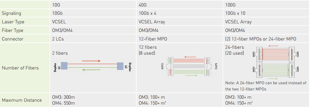
According to the diagram, it is clear that the fiber system should be designed with OM3 or OM4 MMF to support 10G and beyond applications. OM3 supports 10G up to 300 meters, but only supports 40/100G up to 100m. OM4 supports 10G up to 550 meters, but only supports 40/100G up to 150 meters. If planning to support 40/100G in the future, the channel cannot be designed for the maximum distances that 10G can support. You should better design for the application that has the most stringent requirements (usually the fastest data rates) even if the application is a future installation.
Besides selecting the type of fiber, there are several other essential considerations to enable successful 40/100G migration. Which include channel insertion loss, polarity and alignment pins.
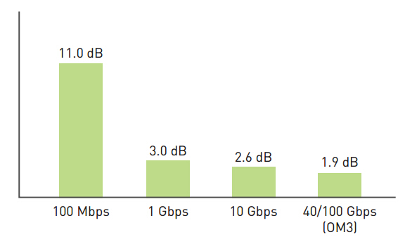
The channel insertion loss is made up of the insertion loss (IL) of the cable, the insertion loss of all mated connector pairs and the insertion loss of splices in that channel. And as the data rate increases from 10 Gbps to 40/100 Gbps, the total channel insertion loss decreases noticeably. The following picture shows total loss budgets for a 100-meter channel at different data rates common to current Ethernet applications. As data rates progress from 100 Mbps Ethernet-based systems to 10 Gbps Ethernet-based systems, the optical loss budgets have shrunk considerably from 11 dB to 2.6dB. 40/100 Gbps Ethernet systems have an even smaller budget of 1.9 dB when using OM3 or 1.5dB when using OM4.
Proper polarity ensures an optical path from the transmit port of one device to the receive port of another device. There are several different methods to maintain polarity, but do remember that the different methods may not be interoperable.
Generally, there are three methods depicted in the TIA standards: Methods A, B and C (for more details click here). And each method requires a specific combination of components to maintain polarity. Here we take duplex signaling which uses an MPO backbone cable, cassettes and patch cords for example. The following shows the component options that are used in specific combinations for each of the polarity methods:
- MPO-to-MPO backbone cables: Type A, B or C
- MPO-to-LC cassettes: Method A or Method B
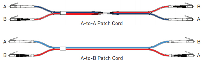
- Patch cords: Type A-to-A or Type A-to-B
Polarity becomes more complicated when migrating to 40/100G because parallel transmission replaces duplex transmission. Parallel optical fiber links integrate multiple transmitters in one transmitter module, multiple fibers in fiber array connectors and multiple receivers in one receiver module. Multiple transmitters and receivers may also be integrated together in a transceiver module.
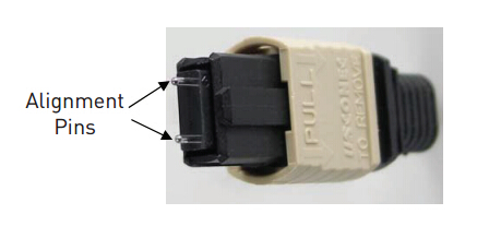
When mating connector plugs that use alignment pins, like the MPO connector, it is critical to ensure that one plug is pinned and the other plug is unpinned. Since general transceivers that accept MPO plugs are pinned, they accept only unpinned plugs. The picture below shows an MPO connector with pins installed.
The pinned connector is typically located inside the panel to help protect the pins from being damaged (i.e. the fixed connector is pinned and the connector that is frequently removed and handled is unpinned). For example, cassettes are typically pinned and trunk cables are typically unpinned. Do make sure the alignment pins are properly cleaned, or it could collect debris around the pins, which results in the two components not mating correctly.
To sum it up, for fiber installation in 40/100G migration, multimode fibers systems are more common and cost effective than single-mode systems for short distances. Select at least OM3, while OM4 will provide longer distance support or more connections over shorter distances. Channel insertion loss is the foundation, so consider high-performance, low loss components. Moreover, consider the polarity method to be used and for parallel transmission uses array connectors, decide which components require pins and which do not.