Category Archives: Fiber Optic Connectors

Serial Transmission vs. Parallel Transmission

We know that in data centers and server farms, when peripherals are attached to a computer, a physical cord is required to send signals back and forth. In this case, the processor can communicate with these devices and send data to them. Communication occurs when the computer sends electronic pulses to the peripheral or vice-versa. Basically, there exist two primary types of digital data transmission: serial transmission and parallel transmission. Then, is there any difference between these two methods of data transmission? How to apply them in data center connectivity? This is what exactly we are going to discuss.

Serial Transmission and Parallel Transmission Overview

For each and every data transfer, the same protocol should be applied to the emitter and the receiver. It enables them to have the same level of information and to know the transfer speed of the data. There are numerous protocols though, and all protocols rely on these two transmission methods: serial transmission and parallel transmission.

serial transmission vs. parallel transmission

Serial Transmission

In serial transmission, bits are sent sequentially on the same channel (wire), one bit at a time. In this way, it reduces costs for wire but also slows the speed of transmission. Also, for serial transmission, some overhead time is needed since bits must be assembled and sent as a unit and then disassembled at the receiver. Serial transmission can be either synchronous or asynchronous.

Parallel Transmission

In parallel transmission, multiple bits (usually 8 bits or a byte/character) are sent on different channels (wires, channels) simultaneously within the same cable, or radio path, and synchronized to a clock. Parallel devices can transfer data in words of one or more bytes at a time. Consequently, there is a speedup in parallel transmission bit rate over serial transmission bit rate, and the cost increasing parallelly since multiple wires cost more than a single wire. As the cable gets longer, the synchronization timing between multiple channels becomes more sensitive to distance. Unlike serial transmission, parallel transmission is considered synchronous.

Transmission Methods Applied in Data Centers

We know that both serial transmission and parallel transmission take a seat in data center connectivity, but in different situations and applications. In the following parts, we will illustrate it in details.

Serial Transmission for 10G Network

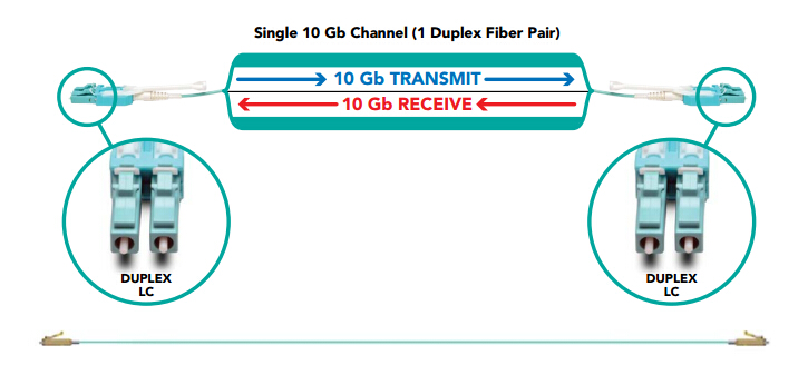
Serial transmission approach is usually employed in 10G fiber connectivity where the data are sent sequentially. A duplex fiber pair that consists of one dedicated transmission fiber and one dedicated reception fiber creates the 10G channel to complete the data circuit. Typically, serial connectivity is achieved by using a duplex LC connector. The LC connector is the most commonly deployed interconnect in data centers, especially for high-density network applications.

serial transmission for 10G connectivity

Parallel Transmission for 40G Network and Above

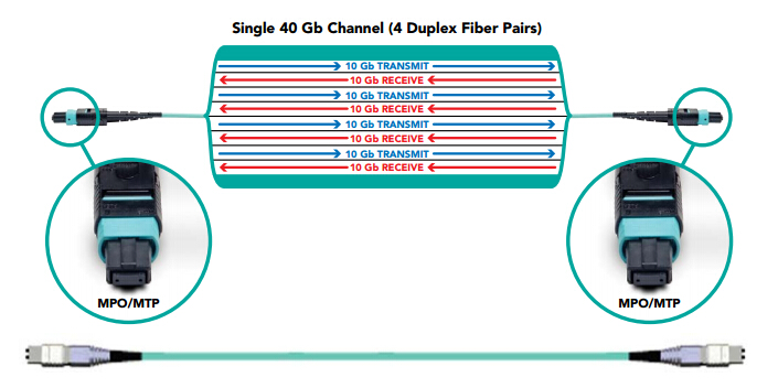
Currently, it’s still not feasible yet possible to adopt a single duplex fiber for beyond 10G network. Although, the technical advancements in serial transmission have raised the limit to 25G, 40G network and above demands for parallel transmission since it can transport more data and achieve higher speeds. For example, parallel transmission achieves the 40G speed by combining four 10G duplex fiber pairs to create a 40G channel. A 100G channel would include ten 10G duplex fiber pairs, and so on. The same principle applies for 120G network and higher.

parallel transmission for 40G and beyond

However, parallel transmission principles can also be applied to 25G duplex fiber pairs to reach even higher speeds or reduce the number of fibers required at a given speed. For instance, a 100G channel would require four 25G duplex fiber pairs instead of ten 10G duplex fiber pairs.

In parallel transmission, MPO/MTP connectors are used to achieve connectivity. They either house 12 or 24 fibers (6 or 12 duplex fiber pairs). This connectivity option finds itself a better place in data centers because it can take advantage of low-cost lasers and multi-mode cables. Equipment designed for speeds of 10G or less has two-strand, duplex fiber ports for serial transmission, while 40G and 100/120G equipment has 12- and 24-strand MPO/MTP fiber ports for parallel optics transmission.

Conclusion

As the basic digital data transmission approaches, serial transmission is often used in 10G connectivity or data transfer with great distances. While for 40G and beyond or short distance transmission, parallel transmission is preferred. Hope you could acquire some useful information from the article, and have a better understanding of these two data transmission methods.

PC, UPC or APC – Selecting the Right Fiber Connector

When describing fiber connector, we often use terms like “LC UPC simplex single-mode fiber connector” or “ SC APC simplex single-mode fiber connector”. Then have you ever wondered what “UPC” and “APC” stand for? Or is there any difference between them? This is what we are going to talk about in this article.

Introduction to Different Kinds of Fiber Connector

Firstly, let’s take a look at how connectors evolve from the original flat fiber connector into the physical contact (PC) connector and then onto ultra physical contact (UPC) connector and angled physical contact (APC) connector.

Flat Fiber Connector

When two flat fiber connectors are mated together, a small air gap is left between the two ferrules. This is partly because the relatively large endface of the connector allows for numerous slight but significant imperfections to gather on the surface. However, it is not much use for single-mode fiber cables with a core size of just 8-9 um, hence there naturally comes to the necessary evolution to physical contact (PC) connectors.

Flat Fiber Connector

Physical Contact Connector

The PC connector is similar to the flat fiber connector but it is polished with a slight spherical (cone) design to reduce the overall size of the endface. Which helps to decrease the air gap issue faced by regular flat fiber connectors, resulting in lower optical return loss (ORL), with less light being sent back towards the power source.

Physical Contact Connector

Ultra Physical Contact Connector

Ultra physical contact connector (UPC) is built on the convex endface attributes of the PC, but with an extended polishing method, which creates an even finer fiber surface finish. This results in lower back reflection (ORL) than a standard PC connector, allowing more reliable signals in digital TV, telephony and data systems, where UPC today dominates the market. UPC connectors do have a low insertion loss, but the back reflection will depend on the quality of the fiber surface and, following repeat matings/unmatings, it will begin to deteriorate.

Ultra Physical Contact Connector

Angled Physical Contact Connector

The tendency is that the industry needs a connector with low back reflection, that could sustain repeated matings/unmatings without ORL degradation. And this brings us the angled physical contact (APC) connector.

Although PC and UPC connectors have a wide range of applications, some instances require return losses in the region of one-in-a-million (60dB). Only APC connectors can consistently achieve such performance. This is because adding a small 8-degree angle to the endface allows for even tighter connections and smaller endface radii. Combined with that, any light that is redirected back towards the source is actually reflected out into the fiber cladding, again by virtue of the 8-degree angled end-face. What to mention is that other three connectors are all inter-mateable, whereas the APC isn’t.

Angled Physical Contact Connector

Differences Between UPC and APC

Currently, with UPC and APC connectors dominating the market, these two types are the most commonly seen connectors employed in the fiber optic industry. In this part, we will mainly explain the difference between them. Besides the more obvious difference that UPC connectors are blue while APC connectors are green, the main difference actually lies in the fiber endface.

UPC and APC

APC connectors feature a fiber endface that is polished at an 8-degree angle, while UPC connectors are polished with no angle. UPC connectors are not exactly flat however, they have a slight curvature for better core alignment. With UPC connectors, any reflected light is reflected straight back towards the light source. However, the angled endface of the APC connector causes reflected light to reflect at an angle into the cladding versus straight back toward the source. This causes some differences in return loss, which is a measurement of reflected light that is expressed as a negative dB value (the higher the value, the better). Industry standards recommend that UPC connector return loss should be -50dB or greater, while APC connector return loss should be -60dB or greater.

Selecting the Right Fiber Connector

With APC connectors being used by most cable companies, other FTTX providers in outside plant applications, and passive optical applications (both GPONs and passive optical LANs). Future higher-speed passive optical networks and other WDM applications that will use higher wavelengths via singlemode fiber will also likely require the reduced return loss of APC connectors. What should be noted is that APC and UPC connectors cannot be mated, in case to cause poor performance or to destroy both connectors. However, when choosing the right connector for your specified application, factors like cost and simplicity should also be considered seriously, not just optical performance. So, it actually depends on the real circumstances and various factors.

Conclusion

It is generally accepted that all of these connector options capture a place in the current market, and we cannot say anyone is better than the others since whether to choose UPC or APC in fact depend on your particular need. Whereas for those applications which high precision optical fiber signaling matters, APC should be the optimum alternative, but for less sensitive digital systems, UPC and APC can both perform equally well.