Category Archives: Connectors & Adapters

Speed Fiber Installation with Field Assembly Connector

The FTTH service nowadays has stretched its reach all around the world, and continues to expand. Naturally, optical fiber constructed to the home is expected to increase in various areas. Under such circumstance, a field assembly connector is commonly employed to streamline the installation process and simplify fiber storage. Thus field assembly connectors have found their position in the following occasions: inside closure, outside cabinet of home, inside ONU, and in premise cabinet. Then, how exactly installers can benefit from field assembly connector? This article will explain it in details.

What Is Field Assembly Connector?

Field assembly connector, also known as fast/quick connector, is a pre-polished, field installable connector that designed for simple and fast field termination of single fibers. Eliminating the need for time-consuming polishing or adhesives. The heart of this fast connector is a pre-polished ferrule, and there exists a mechanical splice inside the connector body. Which enables a positive connection in the mechanical splice, thus achieving low insertion loss termination.

field assembly connector

Field assembly connector not only offers an immediate low loss termination to either single-mode or multimode fibers and are color-coded for ease of fiber identification, but also available for laser optimized 50μm (10G) fibers. It is compatible with 250 µm and 900 µm optical fibers, as well as 900 µm, 2mm and 3mm cordage.

Field Assembly Connector Structure

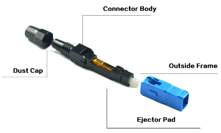
The following picture shows the internal structure of the field assembly connector. When connecting an optical fiber to it, the fiber is built into a ferrule (the end face of which is polished in a factory) of the connector. A factory-installed wedge clip holds the clamping mechanism open while the fiber is inserted. Once the fiber is in place, the wedge clip is removed and discarded.

Moreover, a mechanical splice is found at the end of the ferrule to enable the mechanical fixation of the fiber. This mechanical splice consists of plate A having V groove, plate B which is flat above V groove, and a clamp for the insertion of the two plates. Thus, the optical fiber has been positioned with high accuracy between V groove and plate B, held securely a place by spring power of the clamp.

field assembly connector structure

Benefits and Application

Then, here comes the question: how installers can benefit from the field assembly connector, and where it can be used?

Benefits:

  • Quick, simple and clean solution for terminating connectors.
  • Can be installed in within two minutes, including preparation time.
  • High success rate of connection.
  • Simple assembly process.
  • Factory polished reducing installation time.
  • Stable optical performance is achieved through its use of V-groove mechanical splice technology.

Application:

  • Premise/Enterprise Networks
  • LAN/WAN Connections
  • Patch Panels
  • Equipment Termination
  • FTTx Applications
  • Field Repair/Replacement
  • Equipment Test Leads
Assembly Manual

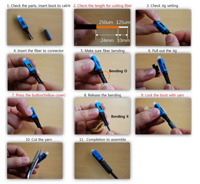
The field assembly connector can be assembled directly on the end of cable just within minutes. Which makes the installation process easy and fast. It requires no specialized tooling except standard fiber preparation tools: a fiber stripping tool, wipes and a fiber cleaver. Even no electrical power supply is needed to assemble this fiber connector. Here we provide a step by step guide to assembly the SC type fast connector for your reference. (see the picture below)

fast connector assembly manual

Conclusion

The factory-polished field assembly connector eliminates the need for any polishing materials, thereby enabling the preparation and termination of optical fiber in a fraction of the time. Meanwhile, it also allows for easy assembly and high performance of connectors. From the standpoint of good arrangement, time reduction, and quality management, field assembly connector is mainly used currently. Furthermore, the prevalence of which is also helpful for spreading the FTTH over the world.

Serial Transmission vs. Parallel Transmission

We know that in data centers and server farms, when peripherals are attached to a computer, a physical cord is required to send signals back and forth. In this case, the processor can communicate with these devices and send data to them. Communication occurs when the computer sends electronic pulses to the peripheral or vice-versa. Basically, there exist two primary types of digital data transmission: serial transmission and parallel transmission. Then, is there any difference between these two methods of data transmission? How to apply them in data center connectivity? This is what exactly we are going to discuss.

Serial Transmission and Parallel Transmission Overview

For each and every data transfer, the same protocol should be applied to the emitter and the receiver. It enables them to have the same level of information and to know the transfer speed of the data. There are numerous protocols though, and all protocols rely on these two transmission methods: serial transmission and parallel transmission.

serial transmission vs. parallel transmission

Serial Transmission

In serial transmission, bits are sent sequentially on the same channel (wire), one bit at a time. In this way, it reduces costs for wire but also slows the speed of transmission. Also, for serial transmission, some overhead time is needed since bits must be assembled and sent as a unit and then disassembled at the receiver. Serial transmission can be either synchronous or asynchronous.

Parallel Transmission

In parallel transmission, multiple bits (usually 8 bits or a byte/character) are sent on different channels (wires, channels) simultaneously within the same cable, or radio path, and synchronized to a clock. Parallel devices can transfer data in words of one or more bytes at a time. Consequently, there is a speedup in parallel transmission bit rate over serial transmission bit rate, and the cost increasing parallelly since multiple wires cost more than a single wire. As the cable gets longer, the synchronization timing between multiple channels becomes more sensitive to distance. Unlike serial transmission, parallel transmission is considered synchronous.

Transmission Methods Applied in Data Centers

We know that both serial transmission and parallel transmission take a seat in data center connectivity, but in different situations and applications. In the following parts, we will illustrate it in details.

Serial Transmission for 10G Network

Serial transmission approach is usually employed in 10G fiber connectivity where the data are sent sequentially. A duplex fiber pair that consists of one dedicated transmission fiber and one dedicated reception fiber creates the 10G channel to complete the data circuit. Typically, serial connectivity is achieved by using a duplex LC connector. The LC connector is the most commonly deployed interconnect in data centers, especially for high-density network applications.

serial transmission for 10G connectivity

Parallel Transmission for 40G Network and Above

Currently, it’s still not feasible yet possible to adopt a single duplex fiber for beyond 10G network. Although, the technical advancements in serial transmission have raised the limit to 25G, 40G network and above demands for parallel transmission since it can transport more data and achieve higher speeds. For example, parallel transmission achieves the 40G speed by combining four 10G duplex fiber pairs to create a 40G channel. A 100G channel would include ten 10G duplex fiber pairs, and so on. The same principle applies for 120G network and higher.

parallel transmission for 40G and beyond

However, parallel transmission principles can also be applied to 25G duplex fiber pairs to reach even higher speeds or reduce the number of fibers required at a given speed. For instance, a 100G channel would require four 25G duplex fiber pairs instead of ten 10G duplex fiber pairs.

In parallel transmission, MPO/MTP connectors are used to achieve connectivity. They either house 12 or 24 fibers (6 or 12 duplex fiber pairs). This connectivity option finds itself a better place in data centers because it can take advantage of low-cost lasers and multi-mode cables. Equipment designed for speeds of 10G or less has two-strand, duplex fiber ports for serial transmission, while 40G and 100/120G equipment has 12- and 24-strand MPO/MTP fiber ports for parallel optics transmission.

Conclusion

As the basic digital data transmission approaches, serial transmission is often used in 10G connectivity or data transfer with great distances. While for 40G and beyond or short distance transmission, parallel transmission is preferred. Hope you could acquire some useful information from the article, and have a better understanding of these two data transmission methods.