With Laser technology combining with fiber optic technology, CATV systems in the field of optical communication have demonstrated unprecedented and irreplaceable achievements in the past few decades. When transmitting optical signals with fibers, fiber attenuation is the main factor that limits the transmission distance. EDFA (Erbium-Doped Fiber Amplifier) designed for CATV long-haul transmission avoids the conversion of optic-electric-optic in CATV long-haul transmission. It amplifies low signal power into high signal power, thus extending transmission distance. This post analyzes EDFA configurations and the utilization in long-haul CATV systems.
EDFA is one of the most prominent achievements in fiber optic transmission technology over the past decade. Because it cleverly combined the laser technology and optical fiber manufacturing technology in the CATV systems and its applications were then rapidly expanded. Originally PDFA and EDFA amplifiers were equally used for CATV systems, but today, EDFA has completely replaced PDFA and become the primary device for fiber optic transmission systems. Why EDFA has leading position on CATV systems? Because EDFA noise and distortion characteristics are better, and its superior characteristics can be clearly seen in the following:
- Operates at wavelength of 1550nm, consistent with C-band where fiber has the lowest loss
- Has higher saturation output power, useful in systems requiring transmission up to 100 km or systems requiring the optical signal to be split to multiple fiber optic receivers
- The signal gain spectrum is wide up to 30nm or more, can be used for broadband signal amplification, especially for WDM (wavelength division multiplexing) system, ideal for radio and data services networks
- Has user friendly interface RS232, easy to control and monitor with computers
- Low noise figure with high stability
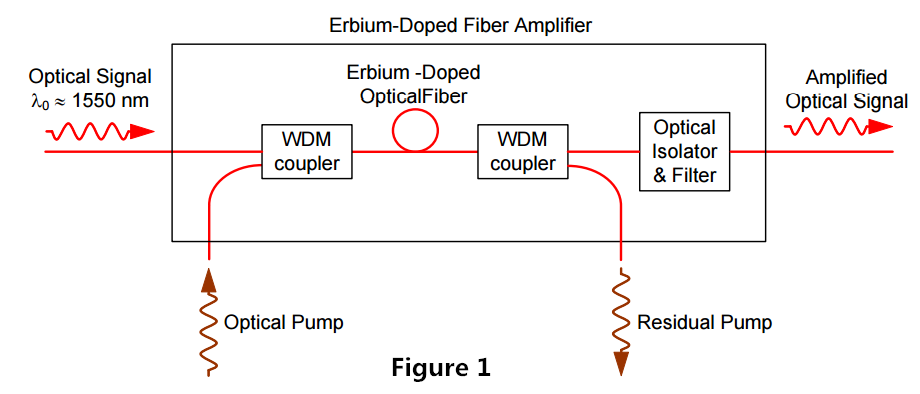
The configuration of a co-propagating EDFA is shown in Figure 1. The optical pump is combined with the optical signal into the erbium-doped fiber with a wavelength division multiplexer. A second multiplexer removes residual pump light from the fiber. An in-line optical filter provides additional insurance that pump light does not reach the output of the optical amplifier. An optical isolator is used to prevent reflected light from other portions of the optical system from entering the amplifier.

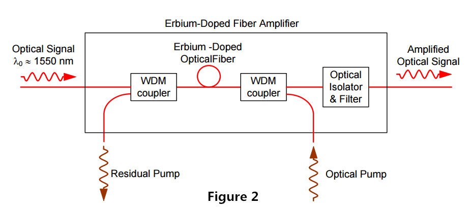
An EDFA with a counter propagating pump is pictured in Figure 2. The copropagating geometry produces an amplifier with less noise and less output power. The counter propagating geometry produces a noisier amplifier with high output power. A compromise can be made by combining the co- and counter-propagating geometries in a bi-directional configuration.

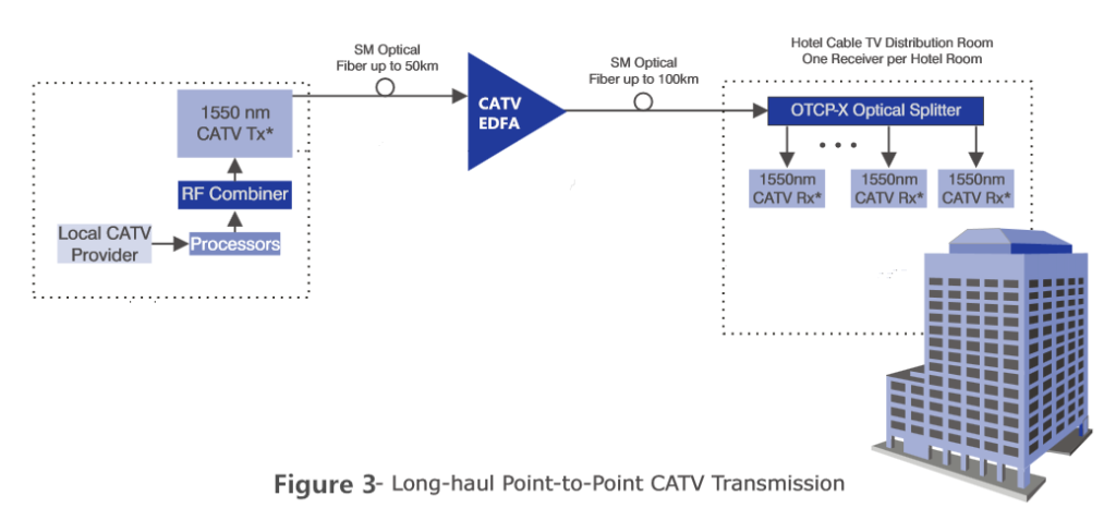
Figure 3 illustrates a basic long-haul CATV transmission system designed to carry 77 channels of CATV signals for 100 km in a basic point-to-point configuration.

As you can see in Figure 3, the local CATV provider sends 77 channels of CATV signals at the transmitting side. After processing and RF combining, those multiple signals are combined into one channel of CATV signal with the wavelengths of 1550 nm. It transmits over a single-mode optical fiber to 50 km. An EDFA amplifier is used at the middle point to amplify the signals to a certain power level, continuing to transmit over a single mode fiber to 100 km. At the receiving side, the 1550nm CATV channel is split into multiple channels of 1550nm CATV signals, serving multiple hotel cable TV users.
EDFA has undoubtedly received wide interest for CATV applications because of its high output power, low distortion and low noise capability. FS.COM supplies optical amplifiers including CATV EDFA, SDH EDFA, DWDM amplifier, etc. The following table lists FS.COM CATV EDFA amplifiers which are available with range of output power from 13 dBm to 24 dBm to meet the requirements of a high-density solution for the large-scale distribution of broadband CATV video and data signals to video overlay receivers in a FTTH/FTTP or PON system.
| Product ID | Part Number | Description |
| 17467 | CEDFA-O13 | New 13dBm 1550nm CATV EDFA Fiber Optic Amplifier |
| 17489 | CEDFA-O17 | New 17dBm 1550nm CATV EDFA Fiber Optic Amplifier |
| 17495 | CEDFA-O23 | New 23dBm 1550nm CATV EDFA Fiber Optic Amplifier |
| 36458 | CEDFA-BA | Customized 1550nm CATV EDFA Fiber Optic Amplifierr |
