Tag Archives: 100 Gigabit Ethernet

OM4 vs OM3

40G bandwidths are now being widely adopted within LANs and Data Centres. And 100G will soon be required within your local networks. Here comes the question: what type of fibre network you should choose when planning your 40/100 GbE migration. You have to consider your cabling infrastructure and how it will meet your current and future data requirements. The cables of choice for data center connectivity and what is recommended by the TIA are OM3 and OM4 laser-optimized multimode fiber. In this post, a comparison between OM3 and OM4 fibers will be given.

OM3- or OM4-Preferred Fibers in the Data Center

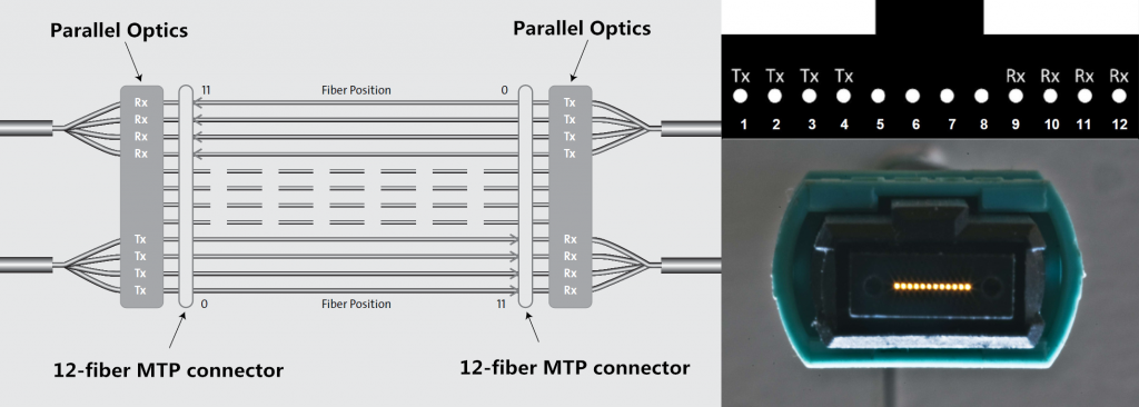
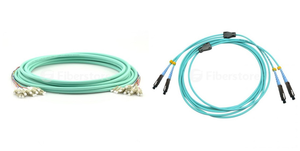
The IEEE 802.3ba 40/100G Ethernet Standard was ratified in June 2010 and specified parallel optics transmission for multimode fiber. OM3 and OM4 are the only multimode fibers included in the standard. OM3 and OM4 laser-optimized 50/125µm multimode fibers are the choice fiber type for connectivity in the data center. The fibers provide a significant value proposition when compared to single-mode fiber, as multimode fiber utilizes low cost 850 nm transceivers for serial and parallel transmission. Below we look at the differences between OM3 and OM4 multi-mode fibers. The picture shows laser-optimized multimode fiber cables.

laser optimised multi-mode fiber cables

Construction of the Fiber Cable

OM3 is fully compatible with OM4. The connectors are the same, the termination of the connectors is the same, the fibre core size 50/125 is the same, and both fibers are laser optimised multi-mode fiber (LOMMF). The difference is just in the construction of the fibre cable. The difference in the construction means that OM4 cable has better attenuation and can operate at higher bandwidth than OM3.

Attenuation: Attenuation is the reduction in power of the light signal as it is transmitted. It is caused by losses in light through the passive components, such as cables, cable splices, and connectors. The difference in OM3 and OM4 performance is in the loss (dB) in the cable. OM4 causes lower losses.

Dispersion: Dispersion is the spreading of the signal in time due to the differing paths the light can take down the fiber. Modal dispersion, which means that the spreading of the signal in time resulting from the different propagation modes in the fiber. OM3 specifies an effective modal bandwidth (EMB) of 2000 MHz/km, and OM4 of 4700 MHz/km, showing that OM4 can operate at higher bandwidth.

Cost Difference

The cost for OM4 is greater due to the manufacture process and economies of scale that the production of OM3 benefits from due to the volumes currently produced. Costs vary depending on the construction type of the cable (loose tube, tight buffered, etc.). OM4 cable is about twice as expensive as OM3 cable. This means that for lots of products such as standard fibre patch panels, MTP cassette modules, fibre patch cords the cost difference is very small (as the volume of cable is small).

What OM4 Gives You That OM3 Doesn’t?

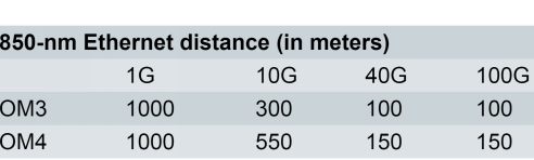
OM4 effectively provides an additional layer of performance that supports these applications at longer distances, as shown in the following picture. OM4 provides an opportunity to future-proof cabling infrastructure, for it can provide a minimum reach of 125m over multimode fiber within the 40 and 100 GbE standards. Additionally, OM4 provides additional reach at extended bandwidth at an overall cost still less than that of an OS2 singlemode system. In other words, OM4 provides a solution that allows more installations to avoid the significantly higher costs of singlemode systems.

transmission distances

Conclusion

It is important to note that OM4 glass is not necessarily designed to be a replacement for OM3. Despite the relatively long-standing availability of OM4, there are no plans to obsolete OM3 fiber optic cabling. Fiberstore offers you a wide range of cable choices for your 40G Ethernet applications, like OM3 and OM4 fiber optic patch cables. And we also offer other 40G components, such as QSFP+ transceiver, copper cable, active optical cable and QSFP+ cable. You can buy from us with confidence.

Parallel Optics Technology Overview

The number of network connections in data centers is on the rise. Data centers have to achieve ultra-high density in cabling. Multimode fiber optics is the medium of the future for satisfying the growing need for transmission speed and data volume over short distances. Parallel optics technology is what you get if you combine both trends—cabling density and the use of fiber optics. It is a suitable solution for high-performance data networks in data centers. This passage provides introductory information on parallel optics technology.

What Is Parallel Optics?

Parallel optics is a term used to represent both a type of optical communication and the devices on either end of the link that transmit and receive information. It differs from traditional fiber optic communication in that data is simultaneously transmitted and received over multiple optical fibers. In parallel optical communication, the devices on either end of the link contain multiple transmitters and receivers. For example, four transmitters on End A communicate with four receivers on End B, spreading a single stream of data over four optical fibers. With this configuration, a parallel optics transceiver can use four 2.5Gb/s transmitters to send one 10Gb/s signal from A to B.

Parallel optical devices are fundamentally different in construction from serial optical devices. Two complementary technologies have enabled the development and deployment of parallel optics devices: vertical cavity surface emission lasers (VCSELs) and the MPO connector. Parallel optic transmission technology spatially multiplexes or divides a high-data-rate signal among several fibers that are simultaneously transmitted and received. At the receiver, the signals are de-multiplexed to the original high-data-rate signal. MPO connectivity is used throughout the parallel optic link and interfaces into the transceiver module. An MPO connector and its connectivity method is showed in the picture below (Tx stands for transmit, Rx stands for receive).

12-fiber-MTP-parallel-connection-1024x366

Applications of Parallel Optics Technology

Parallel optic interfaces (POIs) are a fiber optic technology primarily targeted for short-reach multimode fiber systems (less than 300 meters) that operate at high data rates. Duplex fiber serial transmission with a directly modulated 850 nm VCSEL has been used to date for data rates up to 10G. Current and future protocols expected to use parallel optics include 40G and 100G Ethernet, InfiniBand and Fibre Channel speeds of 32G and higher. IEEE has already included physical layer specifications and management parameters for 40Gbps and 100Gbps operation over fiber optic cable. The uses of parallel optics technology continues to evolve and takes shape as higher-speed fiber optic transmission. Many cabling and network experts have pointed out that parallel optical communication supported with MPO technology is currently a way to equip an environment well prepared for the 40/100GbE transmission.

Why Choose Parallel Optics?

Parallel optical communication uses multiple paths to transmit a signal at a greater data rate than the individual electronics can support. Parallel transmission can either lower the cost of a given data rate (by using slower, less expensive optoelectronics) or enable data rates that are unattainable with traditional serial transmission. Moreover, POIs offer an economical solution that utilizes multimode fiber, which is optimized with VSCEL sources. This means that for speeds faster then 16G, parallel optics, is the most practical, cost-effective solution.

Parallel optics is one technology currently on the market for high data rates networking solutions. Fiberstore is a professional manufacturer and supplier, which offers a large amount of cables and transceivers for your parallel optics applications, such as QSFP+ transceiver and QSFP+ cable. Parallel optical transceivers used for 40GBASE-SR4 and 40GBASE-CSR4 have 10-Gbps electrical lanes that are mirrored in the optical outputs.