Tag Archives: OM4

OM4 vs OM3

40G bandwidths are now being widely adopted within LANs and Data Centres. And 100G will soon be required within your local networks. Here comes the question: what type of fibre network you should choose when planning your 40/100 GbE migration. You have to consider your cabling infrastructure and how it will meet your current and future data requirements. The cables of choice for data center connectivity and what is recommended by the TIA are OM3 and OM4 laser-optimized multimode fiber. In this post, a comparison between OM3 and OM4 fibers will be given.

OM3- or OM4-Preferred Fibers in the Data Center

The IEEE 802.3ba 40/100G Ethernet Standard was ratified in June 2010 and specified parallel optics transmission for multimode fiber. OM3 and OM4 are the only multimode fibers included in the standard. OM3 and OM4 laser-optimized 50/125µm multimode fibers are the choice fiber type for connectivity in the data center. The fibers provide a significant value proposition when compared to single-mode fiber, as multimode fiber utilizes low cost 850 nm transceivers for serial and parallel transmission. Below we look at the differences between OM3 and OM4 multi-mode fibers. The picture shows laser-optimized multimode fiber cables.
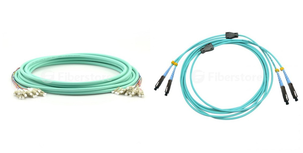
laser optimised multi-mode fiber cables

Construction of the Fiber Cable

OM3 is fully compatible with OM4. The connectors are the same, the termination of the connectors is the same, the fibre core size 50/125 is the same, and both fibers are laser optimised multi-mode fiber (LOMMF). The difference is just in the construction of the fibre cable. The difference in the construction means that OM4 cable has better attenuation and can operate at higher bandwidth than OM3.

Attenuation: Attenuation is the reduction in power of the light signal as it is transmitted. It is caused by losses in light through the passive components, such as cables, cable splices, and connectors. The difference in OM3 and OM4 performance is in the loss (dB) in the cable. OM4 causes lower losses.

Dispersion: Dispersion is the spreading of the signal in time due to the differing paths the light can take down the fiber. Modal dispersion, which means that the spreading of the signal in time resulting from the different propagation modes in the fiber. OM3 specifies an effective modal bandwidth (EMB) of 2000 MHz/km, and OM4 of 4700 MHz/km, showing that OM4 can operate at higher bandwidth.

Cost Difference

The cost for OM4 is greater due to the manufacture process and economies of scale that the production of OM3 benefits from due to the volumes currently produced. Costs vary depending on the construction type of the cable (loose tube, tight buffered, etc.). OM4 cable is about twice as expensive as OM3 cable. This means that for lots of products such as standard fibre patch panels, MTP cassette modules, fibre patch cords the cost difference is very small (as the volume of cable is small).

What OM4 Gives You That OM3 Doesn’t?

OM4 effectively provides an additional layer of performance that supports these applications at longer distances, as shown in the following picture. OM4 provides an opportunity to future-proof cabling infrastructure, for it can provide a minimum reach of 125m over multimode fiber within the 40 and 100 GbE standards. Additionally, OM4 provides additional reach at extended bandwidth at an overall cost still less than that of an OS2 singlemode system. In other words, OM4 provides a solution that allows more installations to avoid the significantly higher costs of singlemode systems.

transmission distances

Conclusion

It is important to note that OM4 glass is not necessarily designed to be a replacement for OM3. Despite the relatively long-standing availability of OM4, there are no plans to obsolete OM3 fiber optic cabling. Fiberstore offers you a wide range of cable choices for your 40G Ethernet applications, like OM3 and OM4 fiber optic patch cables. And we also offer other 40G components, such as QSFP+ transceiver, copper cable, active optical cable and QSFP+ cable. You can buy from us with confidence.
Introduction to MPO/MTP Technology in 40 GbE

The increasing demands of bandwidth and high speed drive the emergence of 40 GbE, and even up to higher in the future. And the high-speed transmission requires high-density data center as the increasing created data need amount of cables and devices which take a lot of space and cost. Data centers have to achieve ultra-high density in cabling to accommodate all this cabling in the first place. Multimode fiber optics is the medium of the future for satisfying the growing need for transmission speed and data volume over short distances. Ultra-parallel connections involve tougher requirements in terms of the components and the handling of the connectors. The MPO/MTP technology has proven to be a practical solution. This article provides introductory information on MPO/MTP technology in 40 GbE.

MPO/MTP—Multi-fiber Connectors for High Port Density

Parallel optical channels with multi-fiber multimode optical fibers of the categories OM3 and OM4 are used for implementing 40 GbE. The small diameter of the optical fibers poses no problems in laying the lines, but the ports suddenly have to accommodate four or even ten times the number of connectors. This large number of connectors can no longer be covered with conventional individual connectors. That is why the 802.3ba standard incorporated the MPO multi-fiber connector for 40GBASE-SR4. It can contact 12 or 24 fibers in the tiniest of spaces. Next part describes this type of connector.

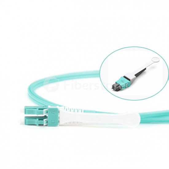
12 Fibers 10G OM4 Harness Cable, 12 Strands, MPO-HD to LC-HD Push Pull TAB Connector

MPO Connectors: Structure and Function

The MPO connector (known as multi-fiber push-on and also as multi-path push-on) is a multi-fiber connector defined according to IEC 61754-7 and TIA/EIA 604-5 that can accommodate up to 72 fibers in the tiniest of spaces, comparable to an RJ45 connector. MPO connectors are most commonly used for 12 or 24 fibers. Eight fibers are needed for 40 GbE, which means four contacts remain non-interconnected in each case. MPO connectors and MTP (mechanical transfer push-on) connectors are no longer terminated on site because of the delicate multi-fiber structure and narrow tolerances involved. MPO/MTP connectors are therefore sold already terminated together with trunk cables. With this arrangement, customers have to plan line lengths precisely but are also assured top quality and short installation times. To achieve lower tolerances and better attenuation values, the American connectivity specialist US Conec developed the MTP connector. It has better optical and mechanical quality than the MPO. An MTP connector consists of a housing and a separate MT ferrule. The MT ferrule is a multi-fiber ferrule in which the fiber alignment depends on the eccentricity and positioning of the fibers and the holes drilled in the centering pins. The centering pins help control fiber alignment during insertion. Since the housing is detachable, the ferrules can undergo interferometric measurements and subsequent processing during the manufacturing process.

Conclusion

MPO/MTP connectors and fiber cables as the important part of the multi-fiber connection system, are designed for the reliable and quick operations in data centers. Fiberstore manufactures and distributes a wide range of MTP/MPO cable assemblies including trunk cables, harness cables and cassettes (or patch panels). And we also offer other kinds of transceiver and cable choices for your 40GbE applications, for example, HP JG709A 40GBASE-CSR4 QSFP+ transceiver, and Juniper QFX-QSFP-DAC-3M QSFP+ to QSFP+ passive copper cable, etc. Futhermore, customized service such as optional fiber counts, cable types and lengths are available.